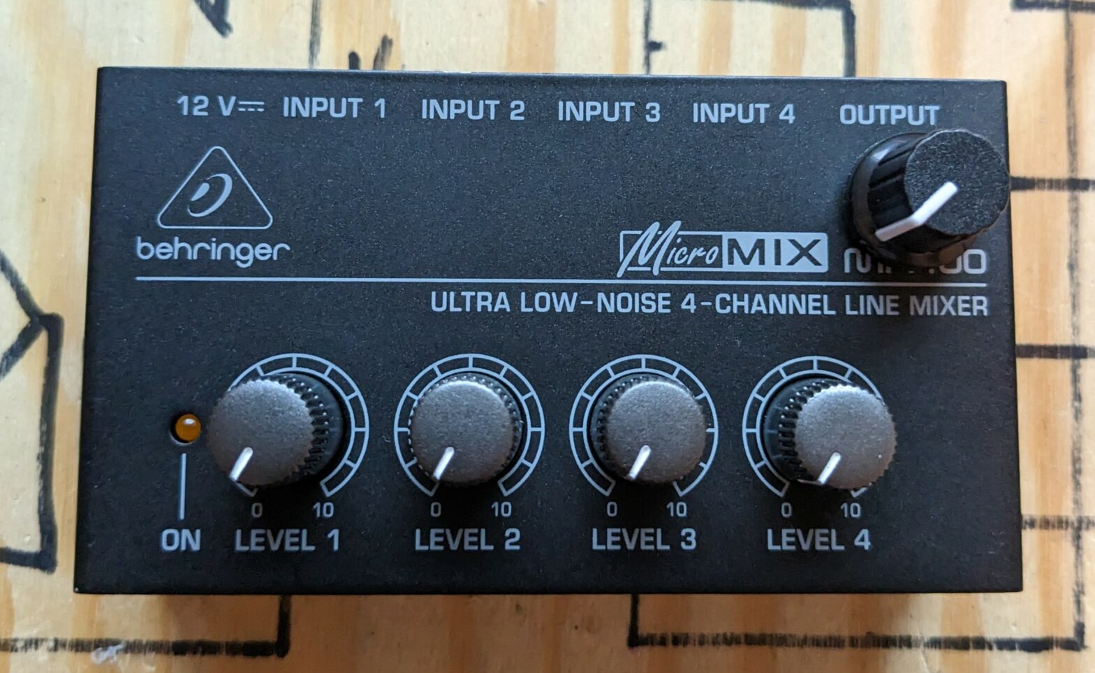
A quick sunday evening mod although performed on a Tuesday. Recently a Behringer TD-3 arrived at my place, no clue how it got there. Honestly, who would just spontaneously order a synth? After reading maffez’ great article I performed some mods that really pushes the little synth to another level! 90s style you would give it an extra push with an overdriven analog mixer of that period. They sound good because they are actually bad. But since a lot of other people are also looking for that sound, they have become quite expensive. So I had to try something else..
The Behringer MX400 is a cheap mixer that is based on 4580 opamps, These opamps have been used in a lot of the ancient mixers. They are cheap, noisy and they give a nice overdriven sound (because they are bipolar, I guess). The mixer contains one gain stage per input and one output stage. The problem is that most of the overdriving occurs in the output stage and not in the input stages. For some reason they gave it a lot of gain in the output, without any means to tame it down. The result is that if you drive the mixer on multiple channels, you end up having a big gwarble-arble of sounds. Even worse the output is way too hot for my audio interface.
So I have to increase the maximum input gain and make the output gain adjustable. Check the following picture:
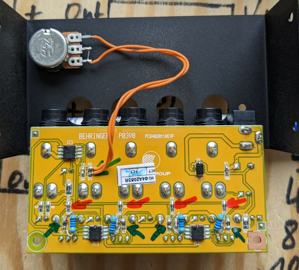
The ICs are all 4580 opamps with the usual two-opamps-in-an-eight-pin-package-pinout. The left side of IC1 generates the half-Vcc voltage aka virtual ground for all other opamps. All others are simply inverting amp circuits with a small capacitor in parallel to the feedback resistor to prevent opamp oscillations and filter out radio stations.
The right side of IC1 is an inverting summing amp and the output stage. R4 to R7 (10k, red) are the channel summing resistors. You can solder further summing resistors to the upper part. I did this in another project that is currently under construction. R2 (47k, green) is the feedback resistor. Using math you can find out that this gives a gain of 47k/10k=4.7 for each channel. That means that the moment you overdrive the input amps, the output amp is already overoveroveroverovedriven (roughly 4.7 times). To avoid that every channel should have an output gain of 1/4, as we have 4 channels. I a 20k log pot in parallel to R2 so I can set the output gain. If for some reason (e.g. to enjoy the 4580s noise) you want to increase the gain, you’d have to remove R2 and use a bigger value.
The input circuits around IC2 and 3 are also inverting amps with the potentiometers being feedback and input resistor (I might add a schematic here later). The maximum gain is set by R11 to 14 (4k7, blue). Lowering their value increases the max gain, I put 470R in parallel. Remember that also decreases the input impedance and can damage your gear or have an impact on the sound! Btw I prefer to use cheap resistors for these parallel-solder-activities since they usually have extremely thin legs. Now all you have to do (actually you don’t have to do any of this) ist to put everything back together and learn what can go wrong in such projects! But don’t blame me for anything that goes wrong 🙂
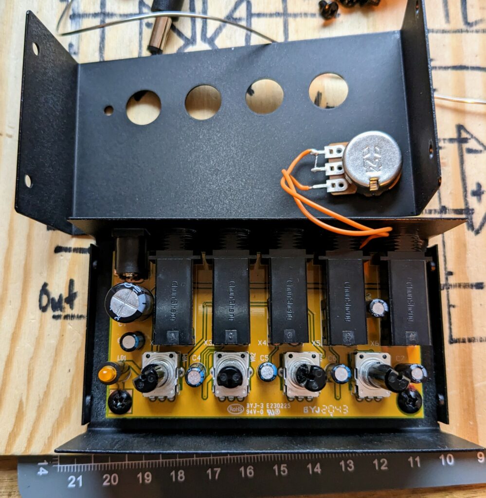
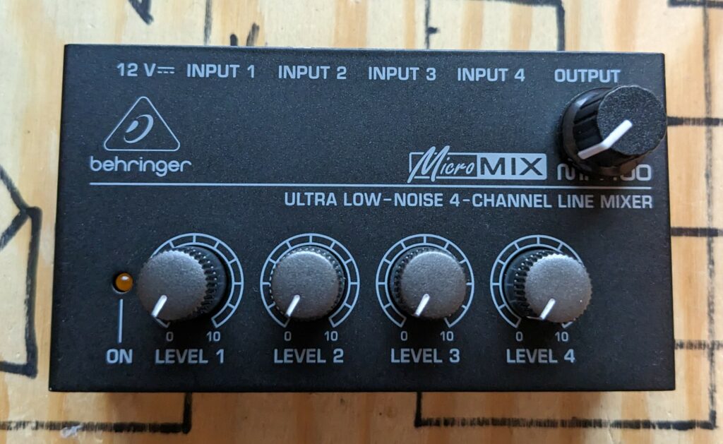
After completing this I realized that driving one channel also makes this channel loud, which is not always desired. So I added extra volume potentiometers to two of the channels and a feedback pot to another one. And obviously I painted the housing.
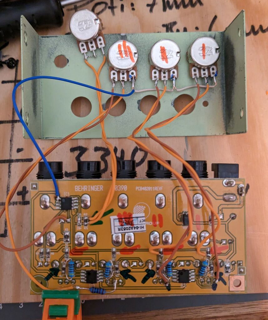
The blue wire is connected to virtual ground, the brown one to the input amps output and the orange one to the output amps input. Of course you have to cut the corresponding Leiterbahn which is the one south of where the orange wire is connected. The feedback pot is wired between the output and the input of channel three via a 1k resistor.
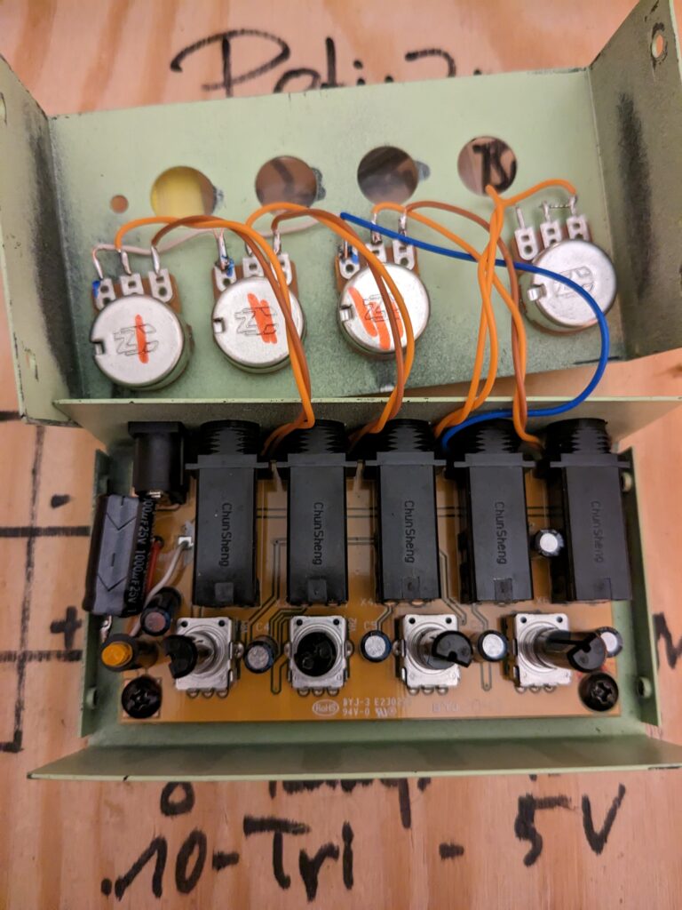
I had to relocate the cap on the left side because it collided with one of the potentiometers. No let’s check the final result:
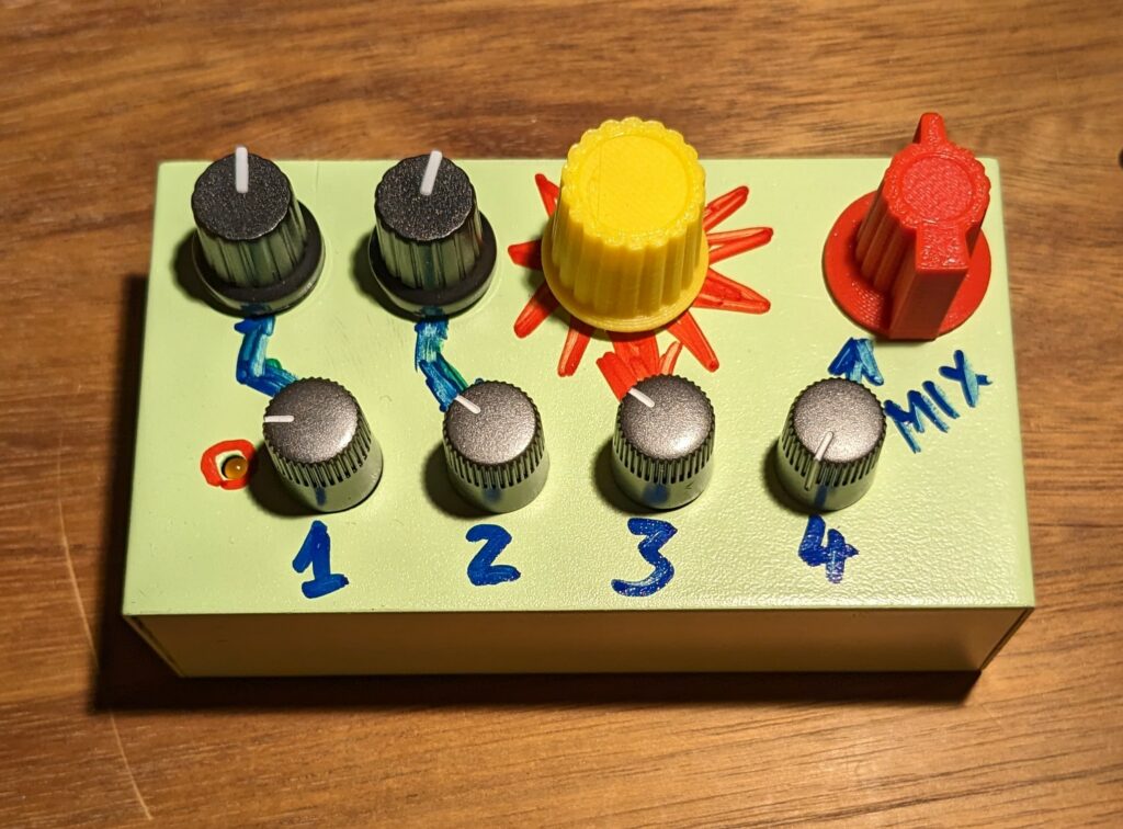
Look how nice it is! Imagine how it could look like in the hands of somebody who can actually paint! Example sounds? Probably, would make sense..
